Determining Which UML Diagram to Use
There are many types of UML diagrams other than the commonly used class diagram. Choosing between them can be a challenge; which type should we use and when? What diagram is right for my problem/codebase? We’ve seen that UML Diagrams are great for designing code but how can we make sure they remain useful when maintaining that same code? I spent some time thinking about these questions and here are some of the answers that I have come up with.
Structure Diagrams
One type of diagrams are the ‘structure diagrams’, they depict information without regard for temporal ordering. They can help to break large projects or features into parts and specify which parts do what and how they interact. The most common example, Class diagrams (example) are very useful, however there are many more underutilized structure diagrams that can help with specific tasks.
If you are working with a large team and need to break a project into many components you are going to need a Component Diagram (example). Combining different parts of your project from different groups of developers becomes much easier with a Component Diagram.
Projects with many different use cases requiring communication between many classes can benefit greatly from Composite Structure Diagrams (example). These show how various components collaborate at run-time and are best used to describe how different classes interact during a complex user action. They combine the usefulness of Use Case Diagrams and Sequence Diagrams.
If you have a large codebase with lots of dependencies Package Diagrams (example) help you get a high level overview quickly and easily. They will immediately unveil what dependencies your project has.
Many client-server projects that use a multitude of frameworks, languages, and hardware should use Deployment Diagrams (example) if they are not already. Typical J2EE projects can often benefit from such diagrams. Deployment Diagrams provide a useful way to visualize the structure of projects spanning many different hardware environments. A project utilizing a cloud server, multiple databases, and a local machine would benefit from a deployment diagram detailing what software runs where and how it communicates.
Behavior Diagrams
When you are dealing with project complexity regarding the actions, behavior, and order in which events occur within your program then you should be using one of the Behavior Diagrams.
Understanding the logic of a specific process, portion of code, or other interaction can be simplified with an Activity Diagram (example). Breaking down a process into individual decisions, loops and chains of events helps make many problems easier to understand. If you are having trouble thinking through a new billing or login process it’s time to break out the Activity Diagram.
If you have a feature where numerous types of users will be using your software in a number of different ways you might need a Use Case Diagram (example). This diagram will help show you a detailed view of how cases and actors are interrelated. Having this information available will help you to determine what actions you will need to support to best accommodate all the users.
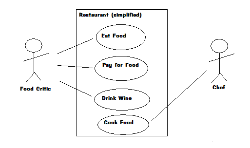
Interaction Diagrams
Behavior diagrams that emphasize object interactions over time are Interaction Diagrams. Designing a system where there are complex relationships between differing code elements requires a fine grain view of how those elements interact over time.
If you have a project with many concurrent actions and need to determine what order they should occur in you may need a Collaboration/Communication Diagram (example). This very specific diagram type is most important when understanding how and in what order multiple classes interact. Communication diagrams are often ignored in favor of sequence diagrams which are able to show the order of events more clearly.
Sequence diagrams (example) are for you if you are designing the sequential logic of your project. A properly created sequence diagram will show each method’s calls separated by class instance in the order they were called. This can be very helpful when tracing the execution of a program or determining if a method’s behavior is correct. Sequence diagrams are not all that useful when dealing with asynchronous behavior or complex loops and iterations.
If you find yourself using many Activity Diagrams and want to see how they are related a Interaction Overview Diagram (example) will be helpful. Each node in an Interaction Diagram can represent another complete Activity/Interaction Diagram. This can be very helpful when dealing with nested logic or complex combinations of logic.
A project that contains many objects that frequently change state over a period of time would benefit from a Timing Diagram (example). Without a such a diagram you may not realize how potential periods of high traffic could intersect and overwhelm your program.
Summary
Not every project needs to use every type of UML diagram. Each project presents its own challenges; hopefully now you are well versed in the potential of diagrams as solutions. A well thought out set of correctly chosen diagrams created during the design process of a project can alleviate many headaches later on in the development cycle.
Image credit: wikipedia
I am writing new articles once every 2-3 months. Interested in getting notified? Sign up here.